
Shear Fracture
Automotive product designers target small radii for springback control, sectional stiffness, packaging constraints, and design features. These small radii lead to new challenges as applications for AHSS grades continue to increase. One of these challenges is an increased sensitivity to crack formation in those designs with small die radius to material thickness (R/T) ratios. Cracks forming at small R/T in AHSS grades are known as shear fractures.
General forming limit curves or other press shop criteria cannot predict shear fractures, nor are they flagged when traditional approaches are used in forming simulation packages. However, these shear fractures do occur in die tryout. Shear fractures are another form of local formability failure associated with multiphase AHSS such as DP and TRIP.
Shear fractures on AHSS may exhibit similarities to edge fracture, specifically the absence of necking prior to failure. This is in contrast with global formability failures, which are characterized by significant thinning near the fracture. Shear fractures occur almost immediately (within 1 mm of displacement) after reaching maximum load, meaning there is essentially no post-uniform elongation. This is contrary to the tensile behavior where significant post-uniform ductility remains prior to fracture.K-9
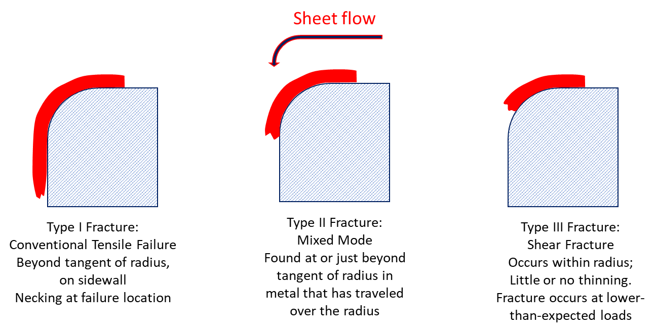
It is helpful to describe the characteristic differences between conventional tensile fracture and shear fracture, as shown in Figure 4. A conventional tensile fracture is called a Type I fracture, and has been the typical fracture type historically encountered. Type I fractures occur off the radius, and is preceded by necking or metal thinning. Successful prediction of this type of fracture occurs with conventional application of strain analysis and Forming Limit Diagrams. This is in contrast with shear fracture – categorized as a Type III fracture – which occurs within the die radius, with no thinning from necking (typical for local formability failures). Type II fractures occur at or near the tangent of the radius in metal drawn over the radius.
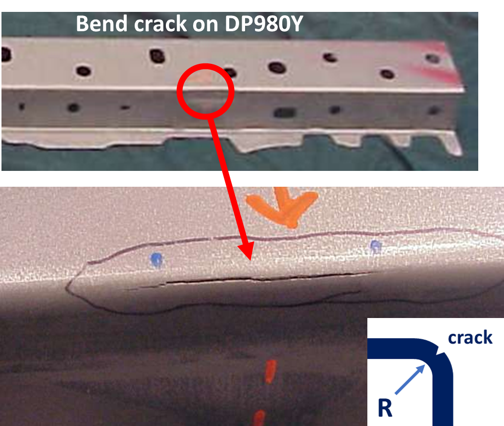
Figures 1 and 2 highlight the appearance of a crack on the bend radius caused by shear fracture. No thinning is observed, which is consistent with failures limited by local formability concerns.
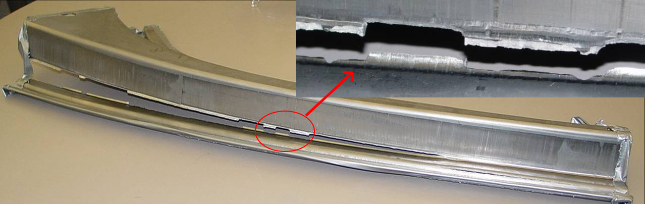
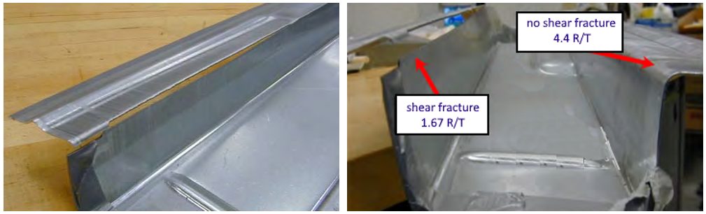
Figure 3 shows a typical shear fracture on a DP780 part viewed from different angles. The shear fracture occurred on the sharp radius on the left whereas the larger radius on the right experienced no failure. Depth of draw and draw bead configuration were the same on both sides of the draw panel. Restraining force was also similar on both sides of the blankholder. The significant variable was the die radius.
Shear fracture is sensitive to rolling direction. If the radius is running in the rolling direction, the bend will be transverse to the rolling direction which is the worst-case scenario when trying to avoid shear fracture. Understanding the directionality of minimum R/T ratios when designing the part to avoid shear fractures is therefore important.
One study evaluated DP780, which discovered a critical minimum R/T of 5 to avoid shear fracture, although this varied with back tension and pulling speed. At all R/T ratios tested, the samples oriented so the bend radius was parallel to the rolling direction failed at lower stress than if the bend radius was perpendicular (transverse) to the rolling direction. Tighter R/T magnifies this effect, as does a higher strength grade.
At 1.5 R/T, shear fracture with bends perpendicular to the rolling direction occurred when the stress reached 81% of the tensile strength, where in samples with the bend parallel to the rolling direction, failure occurred at 66% of the tensile strength.S-21
Microstructure also plays a role. Phase distribution uniformity, fine microstructural phases, and a decrease in hardness ratio between martensite and ferrite all increase formability as measured by the smallest achievable R/T resulting in split-free panels.W-4, H-6
These are the same factors that result in improved hole expansion values.
Forming Limit Curves are the limiting strain states based on the onset localized deformation, or necking. Generating conventional FLCs typically involves using a 100mm diameter hemispherical punch to deform 1mm to 2mm thick sheet steels, resulting in R/T ratios of 25 or higher.
Many decades of use have shown that conventional FLC approaches can be used to assess part robustness and predict failure in areas having large R/T ratios and failure modes affected by global formability. These show up as Type I fractures.
When the R/T ratio is within the shear fracture limit but above the simple bending limit (no stretching imposed to bending), failure may occur in the radius or outside the radius, depending upon the tension level applied during forming.
If the failure occurs inside the radius, the failure limit derived from the shear fracture tests should be used as the criterion to predict failure. Finally, when the R/T ratio is smaller than the limit from the simple bending test, the failure occurs in the radius.
In addition to large R/T, most Forming Limit Curves are generated from tests are conducted at a very low strain rate, maintaining an isothermal condition (no heat generated from deforming the sheets). While these conditions are consistent with those adopted for the simulations, they differ significantly from those encountered in industrial practice.
Ignoring the role of deformation-induced heating is one of the most significant reason for the limited success of shear fracture prediction in conventional forming simulation. Strain rates for stamping are typically 1,000x to 10,000x greater than the strain rates for tensile testing.
Contact between the sheet metal and the tooling at tight radii also drives up the local temperature. Maximum temperature at the die-sheet interface of 70°C has been found on DP590, but 105°C for CP800.F-6 Stamping DP780 leads to die temperatures of 180°C and blank temperatures of 108°C.P-11 Stamping DP980 produces contact temperatures of over 200°C in certain conditions.F-28
Using a simulation model that accounts for the thermal effects of forming and the associated response in the sheet metal, along with the traditional mechanical deformation response, has been shown to dramatically improve simulation accuracy to predict when shear fracture will occur.K-9, S-20, S-22
Therefore, it is important for the part designer to design an appropriate die radius for a given AHSS product and forming conditions / processes used to manufacture the part.
Forming simulation is an excellent tool to derive an appropriate die radius for the specified part and forming process, recognizing that the failure criterion in the simulation must incorporate all conditions and failure modes encountered, including shear fracture.
Key Points
-
- AHSS grades are at risk of crack formation in designs with small die radius to material thickness (R/T) ratios. These cracks are known as shear fracture.
- The strains associated with shear fracture are below that which are associated with the Forming Limit Curve.
- As with edge fractures, shear fractures are also a function of microstructure, strength level, and rolling direction. Consider these variables when designing parts and conducting die try-outs with prototype steel.
References
- K-9Citations: K-9. J.H Kim, J.H. Sung, K. Piao, and R.H. Wagoner, “The shear fracture of dual-phase steel,” International Journal of Plasticity 27 (2011) 1658–1676, dx.doi.org/10.1016/j.ijplas.2011.02.009.
- F-5Citations: F-5. J.R. Fekete, “Manufacturing Challenges In Stamping And Fabrication Of Components From Advanced High Strength Steel,” International Symposium on Niobium Microalloyed Sheet Steel for Automotive Application, Edited by S. Hashimoto, S. Jansto, H. Mohrbacher, and F. Siciliano, TMS (The Minerals, Metals & Materials Society), 2006.
- D-7Citation: D-7. Courtesy of J. Dykeman, Honda.
- U-6Citation: U-6. U. S. Steel Corporation, "Mechanical and Material Test Lab Strip Draw Test."
- W-4Citation: W-4. M.S. Walp, A. Wurm, J.F. Siekirk III, and A.K. Desai, “Shear Fracture in Advanced High Strength Steels", SAE Technical Paper 2006-01-1433, SAE 2006, doi.org/10.4271/2006-01-1433.
- S-19Citation: S-19. H.C. Shih, "An Experimental Study On Shear Fracture Of Advanced High Strength Steels", Presented at 2009 Great Designs in Steel, Sponsored by American Iron and Steel Institute.
- S-20Citation: S-20. J.H. Sung, "The Causes of “Shear Fracture” of Dual-Phase Steels," 2010 Dissertation, Ohio State University.
- S-21Citation: S-21. H.C. Shih, M. Shi, D. Zeng, and Z. Xia, "Development of Empirical Shear Fracture Criterion for AHSS," SAE Int. J. Mater. Manuf. 3(1):670-675, 2010, doi.org/10.4271/2010-01-0977.
- H-6Citation: H-6. A.W. Hudgins, D.K. Matlock, J.G. Speer, J.R. Fekete, and M.S. Walp, “The Susceptibility to Shear Fracture in Bending of Advanced High Strength Sheet Steels,” Proceedings of Steel Properties and Applications Conference (2007 MS&T), edited by L.C. Oldham, AIST, Warrendale, PA, 2007, pp. 145.
- F-6Citation: F-6. A. Fallahiarezoodar, R. Peker and T. Altan, “Temperature Increase in Forming of Advanced High-Strength Steels Effect of Ram Speed Using a Servodrive Press.” Journal of Manufacturing Science and Engineering - Transactions of The ASME 138 (2016): 094503., doi.org/10.1115/1.4033996.
- F-28Citation: F-28. A. Fallahiarezoodar and T. Altan, “Lightweighting in the automotive industry using sheet metal forming, Part 2: Optimization of process parameters,” Stamping Journal, March / April 2016.
- P-11Citation: P-11. M.P. Pereira and B. Rolfe, “Temperature conditions during ‘cold’ sheet metal stamping,” Journal of Materials Processing Technology, Volume 214, Issue 8, August 2014, P. 1749, doi.org/10.1016/j.jmatprotec.2014.03.020.
- S-22Citation: S-22. J.H. Sung, J.H. Kim, R.H. Wagoner, “A Plastic Constitutive Equation Incorporating Strain, Strain-Rate, And Temperature,” International Journal of Plasticity 26 (2010) 1746–1771; doi.org/10.1016/j.ijplas.2010.02.005.